
Shenzhen-Huizhou Intercity Railway

Φ 9.13m CREG EPB TBM
Depth: 41m
Project year: 2025


Project Summary
Route Overview:
Location:
Overburden ranges from 12.5 to 171.1m, with longitudinal slopes of 28‰, 11.4‰, and 2‰
Developed fissures running along both sides of the fault zone. It worsened water ingress, with rock instability
Tunnelling Work
Tunnel passes through slightly weathered sandstone, slate and fault fracture zones
Groundwater table elevates between 38.73 and 48.38m. The tunnel is at 41m.
Construction Difficulties
High groundwater content, fissures, and low clay content caused severe dilution of conditioning agents (e.g., bentonite and chemical slurry) by groundwater. This prevented the formation of "plug" at the screw conveyor gate, leading to serious water and soil spewing:
Fissures prevented air pressure buildup at the face
Rich groundwater and low clay content reduced effectiveness of conventional conditioning slurries;
Intermittent muck flow causes poor belt transport and slurry spills into the tunnel, increasing cleanup time.
Project halted for 12 months after finding 0 solutions

Before Jello-Mud was implemented at this jobsite. Photos taken by the contractor at the screw conveyor
Jello-Mud Results
Jello-Mud is injected into excavation chamber (positions 3 and 9), the cutterhead rotates for 20 minutes (0.5–1rpm, adjusted based on mucking conditions), no discharge from the screw conveyor at this stage; after mixing, the screw is slowly activated to observe discharge. Initial adjustment took 2–3 rings, with a 50% replacement of muck in the excavation chamber (60m³ Jello-Mud). During subsequent tunnelling, injection continues with a dosage of 15–20% (18–24m³).
To stabilize face pressure, Jello-Mud is injected through two upper-side holes in the middle shield. The initial injection volume is about 9m³; for each ring thereafter, inject 5–6m³, adjusted based on chamber pressure fluctuations.
Stable excavation chamber pressure - The air pressure system is set to 4.1bar during advancing.
After injecting Jello-Mud into the shield surrounding and excavation chamber, air loss is 1m³ every 3 minutes.
Stable screw conveyor discharge
Spewout solved within 1 day with Jello-Mud

Jello-Mud injection points (reserved grouting holes on TBM, no need to retrofit new injection holes)
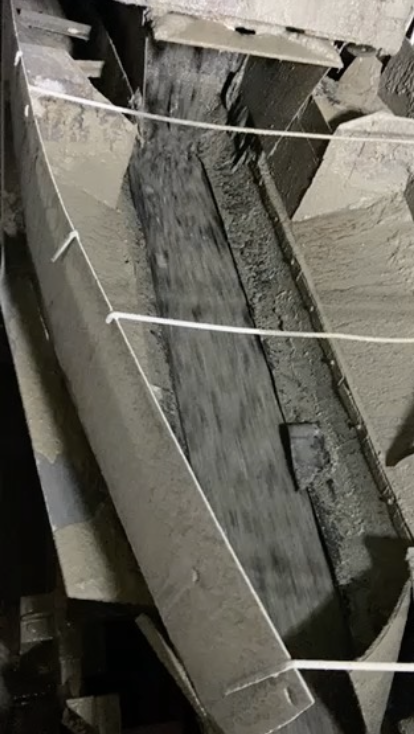

Photos taken after Jello-Mud implementation by Balsam Laboratory technician. Screw conveyor discharge stabilized.